Tuesday, January 26, 2021

Bench Grinder Rescue and Upgrades

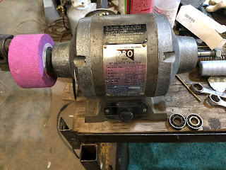
This has been done to death on YouTube so no point in a video.  This may seem like a diversion but I need a decent setup to grind lathe tools.  When this fell in my lap it was time to act.


1/2 HP, 6" WHEEL, 3450 RPM, 60 Hz, 110V, 4 Amp, Single Phase.  Four amps is good for a 6" wheel grinder.   That is about the top of the range for similar.  But it does have a 1/2" shaft and some are 5/8".  As long as its not bent it should not much matter.

While helping a friend I spotted a bench grinder laying outside.   He said it would not start and I could have it but he wanted the wheels.

Did not find a start cap under the base.  Took the end bells off and it looks like the bearings have been spinning on the shaft.  Replaced them and it started although sluggish.  I vibrated a lot as expected.  Forgot to look for the cap inside the bells.  Will be taking it apart again so not a problem.

Grinder with old bearings and cup wheel.

I plan to use this unit with the pink cup wheel.  The hole in the wheel is 20mm and the shaft is 1/2".  So I turned a bushing on the Atlas.   The OD came out great but the ID reamed out a bit larger than I was shooting for.  Still might work.   If not easy enough to make another. 

Next: turn the flanges/washers that support the stones.  But first I need to recheck the motor shafts to ensure they are uniformly 1/2".  Seen on YouTube where this is not always the case.  Have also seen distortions where the flange rests from abuse.  Need to check that too.

Took some scotch brite after the shafts this morning.  Used the 10ths indicator on the left side.   Did not have a good mount for the motor but it looks like it is within 2 or 3 th's.   Way good enough.   
Hand tightened the wheel between 2 of the factory sheaves without additional cardboard for cushioning.  Flipped it on and it vibrated like crazy so I quickly shut it down, did not get to full speed.

The plan is to make a new sheave for the backside and incorporate the bushing into it to make it as long as possible. This will ensure alignment between the sheave and the shaft.  The sheave will be fixed perpendicular to the shaft.  Then any runout will be due to the stone.

I know I have a 10 under reamer.  I may use it by hand after drilling the next size under 1/2.  Have to look at the boreing bars.  It would be even better if I could bore it.


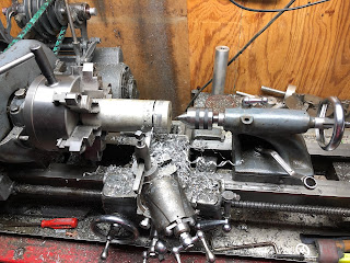
The stock I will be using for the grinding cup's hub.  Parted it about 1/2 the diameter then finished cutting it on the bandsaw.


The plan is to do all concentric operations without flipping the part.  Hogged off most of the material then switched to a threading tool to relieve the back and define the intersection between the hub and sheave.   The OD of the hub is such that the stone will go on but its too tight.  Don't want to sand it to get the last bit because I want it to stay as concentric as possible.
Drilled and then bored the half inch hole.    Could be tighter but good enough.   Reduced the OD to where it still is a push fit which is great.  The hub and factory outside sheave run full speed with very acceptable vibration.  Add the wheel and the grinder walk away.  Have never let it come to full RPM.

Need to figure out how to balance it.   Thinking a strip of soft lead on the inside of the cup.  Need to come up with a 1/2" arbor for this.  Then need to rig up something to roll it on.   Maybe a couple of bars.


Random pics2


Saturday, January 9, 2021

Lathe feet

People were shorter 100 years ago when the Sidney was new.   So I made feet to raise it to a more comfortable working height.   About 4" based on the Diet Dr Pepper bottle in the last image.

These feet were made shortly after first chips.   They are turned aluminum castings.  That was 3 years ago.   They looked a bit better back then but still do the job and look decent IMHO!   Truthfully I stopped noticing them long ago.

The bottom of each lathe leg has a bolt hole for bolting down the lathe.   There is an upside down carriage bolt in these holes with a washer and nut on top and bottom   This provides the adjustment.   The rounded head of the carriage bolt drops into a hole resting on the top of the upside down rounded head.

If the lathe comes to a sudden stop it will twist lifting a bolt.  I don't recall how deep the holes are or know how far they lift when this happens.  Whatever depth it is seems to be enough.  Next time I have occasion to lift the lathe I will check the depth and update here.


A large thick washer might support the leg better.From this angle you can see the offset hole is kind of scary.   


Monday, January 4, 2021

My version of a push stick or block


Dennis wanted to see my version of a push stick. More of a push block but let's not mince words.


It has a pistol grip that is roughly contoured to fit my hand.  The material as used pallet stickers like theses.  I stacked a few sections, rough cut the shape on the bandsaw and smoothed it on the belt sander.

The sole get chewed up by the saw blade on some cuts.  These are the cuts where you want to push both the work and the offcut past the blade.   Or when the blade is too close to the fence for the stick to pass between the blade and fence.

When it becomes unusable I cut off the bulk of what's left on the bandsaw and run the stick over the jointer to get a nice glueing surface.   Now I can imagine people saying I don't have all that fancy equipment.  One could easily use velcro or 2 sided carpet tape to attach the sacrificial sole.  

Rather than notch the sole to catch the work just glue on a small block  

Many time I will use a more traditional push stick to hold the work against the fence while pushing it through with this one.