A lot of images are included here to aid in reassembly.

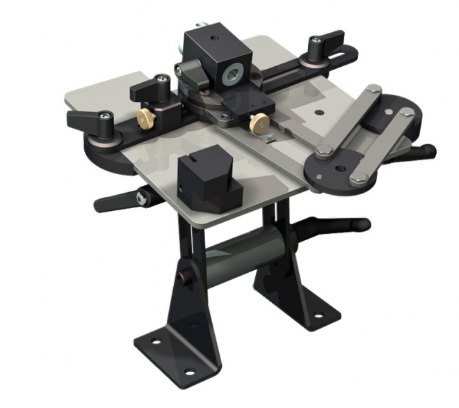
This is the unit I am starting with. Sorry about the light from the windows. In its first life a circular saw was suspended from the arm and it was a stand in for a radial arm saw.

It is covered with years of filth and oxidation.
The arm pivots but reluctantly.

The thing has two protractors. One at the base of the leg and a plastic one clamped to the bar about 1/2 way up here.
Two large nuts on this threaded bar clamp the upright to particle board. The threaded rod is behind the particle board. On could place it anywhere, like on a workbench.


To aid in disassembly the rails have been hit with a bit of sandpaper.
-----------------------------------
Tuesday
Tuesday
Found an excellent video by JSK-koubou. Angle Grinder Sliding Cutting Jig
 Continued with the grinder bracket. The plan is to weld a wider bit of flat bar to this and bolt the flat bar to the wood handle. The first bend interfered with the second bend. They make hook shaped dies for this purpose. So I had to finish it by hand. The top is got a little curved in the process. It is just a little too narrow to fit over my anvil so I can't easily hammer it out. Maybe good enough.
I have been thinking about mounting the handle to the bracket on the linear bearing. Initially I will make it simple as possible just to get it going. Then use a bearing of they type from the HF cement mixer drum. If it is not too big.
The vinegar the bracket is soaking in has slowed down or stopped working. Don't know if it is used up or if the rust has stopped reacting with it.
This is what I want to do but simpler than want I was thinking. My linear bearing setup is horizontal instead of vertical but a stout bit of angle iron will fix that. Initially I will build it without the nice thrust bearing he used but should work. Am making a little different setup to attach the grinder to the wood. Plan on making it so I can more easily swap out the grinder and not change the wood. Each grinder will have a metal bracket with the same spacing between the bolts.
I have cut the mounting angle and have it soaking in vinegar. It is old and pitted but quite thick so will be OK. If this works I may treat it to a sandblast and some bondo. Maybe.
Started work on the mounting bracket for the grinder. Bent one up in the press brake but the arms going to the holes on the grinder need to be slightly longer so it can pivot. Had to go downtown and pickup a bould of M8 bolts.
New fence on the press brake is working well. Currently it is only constrained from moving away from the dies. Thinking about some way to prevent it from moving toward the dies. That is not too much work. EDIT: The easiest thing would be to make the spacer block used to set it L shaped so they can hook over the fence and not fall down. That should be good enough and really only needed when making several.
If all goes well I can have the grinder mount finished tomorrow and make the first version of the wood handle. Thinking of attaching a 3 or 4" steel disk to the face of the wood handle and have it rotate against the mounting angle. That or use a ball bearing from stock. Thinking the plate would give more stability
---------------------------------------------------------------
Wednesday - snowed last night, high of 40F today.
 Continued with the grinder bracket. The plan is to weld a wider bit of flat bar to this and bolt the flat bar to the wood handle. The first bend interfered with the second bend. They make hook shaped dies for this purpose. So I had to finish it by hand. The top is got a little curved in the process. It is just a little too narrow to fit over my anvil so I can't easily hammer it out. Maybe good enough.
I have been thinking about mounting the handle to the bracket on the linear bearing. Initially I will make it simple as possible just to get it going. Then use a bearing of they type from the HF cement mixer drum. If it is not too big.
The vinegar the bracket is soaking in has slowed down or stopped working. Don't know if it is used up or if the rust has stopped reacting with it.
I should explain that I am working on this from 2 directions. From the grinder out and from the linear bearing out. When they are finished I just need to do the bits in the middle.
Should mention I am a bit apprehensive about this becoming a rabbit hole. To use the ball bearing I would need to cast and machine a few parts. That could take a few more days thus the KISS for now.
Should mention I am a bit apprehensive about this becoming a rabbit hole. To use the ball bearing I would need to cast and machine a few parts. That could take a few more days thus the KISS for now.
Am also concerned about the grinder hanging off to the side of the linear rails. JSK-koubou arranged his rails one above the other. Mine are side by side with the angle grinder to one side. The grinder is light it should work.
Going to have some popcorn then go back out and finish the grinder bracket. Ah maybe save the welding till tomorrow when the sun is out. I hope. Took the linear bracket out of the vinegar. Maybe drill the holes in it.
Going to have some popcorn then go back out and finish the grinder bracket. Ah maybe save the welding till tomorrow when the sun is out. I hope. Took the linear bracket out of the vinegar. Maybe drill the holes in it.
Took a nice long break. Took the linear bearing bracket out of the vinegar and blued it and then took the linear bearing apart. The rollers look to be phenolic. Will see when they are cleaned. Has white grease with a bit of a yellow tint. Lithium maybe.
Have the bearing sorted. Do it now and not have to revisit it. Machine an aluminum bearing holder with a flange from a pulley blank. Bolt the flange to the wood handle with a cutout for the bearing bit. Use threaded rod for the axle. Machine a tube that threads over the axle with the same OD as the bearing ID. Use loctite bearing retainer to glue the bearing into the holder. The stack up for the bearing will be all metal with the handle bolted to the holder flange. Bore the center hole for the flange with a forstner bit and turn the OD of the flange for a nice fit.
There is so little side load on the bearing that any will do. Will try for a deep groove if I have one.
-----------------------------------------------
Friday
Last night in the wee hours I glued up a blank for the handle. About3AM I ran it through the surface planer.
Today I cleaned the linear bearing in the ultrasonic cleaner and lubed it. Used dawn for the die cast parts but one. That went in with the bolts and such with royal purple. It dulled the surface.
Shortened one leg of the mounting plate and drilled holes to attach it to the linear bearing. Shot a short video and uploaded it here. Does not seem to work so may have to use YouTube.
Shortened one leg of the mounting plate and drilled holes to attach it to the linear bearing. Shot a short video and uploaded it here. Does not seem to work so may have to use YouTube.