Thursday, July 16, 2020

Mig Tips for Propane Burners

Chirpy regarding mig tips for burners 
mig tips are fine tbh
025 for 1/2" NPT pipe, 030 for 3/4" NPT, and 035 for 1" NPT pipe
perfect sizes actually based on orfice sizes

Wednesday, July 15, 2020

Muller Build July 15-


Left to do

Maybe in this order
  1. Mount the drum to the stand
  2. Make a mount for the top bearing.
  3. Cobble together the drive bits.
  4. Make the arm, plows and roller(s)
  5. Make the trap door for emptying
  6. Wheels and maybe a fold up or detachable hitch

Mounting the drum

But the belt setup going to the drum is a fixed length which means the location of the drum and and 2nd spindle are inter dependent.   I want the drum centered left to right but can fudge a few inches front to back.    Need to mock this up. Again.

I am not crazy about welding mounting brackets to the bottom of the drum.   Maybe use long angle iron running front to back and weld on the outside perimeter of the drum where there is already a weld. Perhaps a few tacks along the bottom if needed.

If I don't need to make the drum adjustable for belt tension, and I don't think I will.  It can be attached to these angles with pins instead of bolts.   The idea is that if for some reason I need to break it down it would be a lot faster if it did not require wrenches. 

The drum can be mounted with just 2 angle irons which run along the outside of the frame.  I can add these mounts and hold off on drilling holes for pins or bolts until I get the drive sorted.  There are 2 fair sized runs of angle iron left from the saw.  Maybe these can be used,  trying not to use bed frame.

11AM

Attempted to accomplish this with no luck.  Played with the parts and figured maybe I should cut the stand down.   It and my deep drum together are too much.  I can take 10 inches off the stand and it will provide a more stable base.   Was thinking about mounting the drive on the end but realized the side might be a better deal.  Less folding, or changing direction.   The small 2.5" pulley I selected for the 1st shaft will not work.  Its hole is too small.   Found that after pulling it off a motor.  Need to take another look around and if I can't find on I will turn one.  Leave a stub on it for chucking it in the lathe.  The I can make it a bit over size and turn it down to get it right.  If I end up sizing this shaft too there will be plenty of meat for the larger shaft.   So it looks like I need to turn two pulleys.  Luckily I 'THINK" I already have cast blanks that will works.   So that will be my afternoon.   But first I want to make the missing pin from the Atlas lathe compound.  With luck I can find a pin in the assorted unknowns and bevel the end to match instead of turning one down.

This is wrong.  The 2" pulley on the second shaft already  exists it is the small toothed pulley.

Maybe the top bearing mount should also be a quick release type of thing.  Make changing out the stuff inside the drum easier.  That way I can do things other than mull sand.  No plans but would like the option.

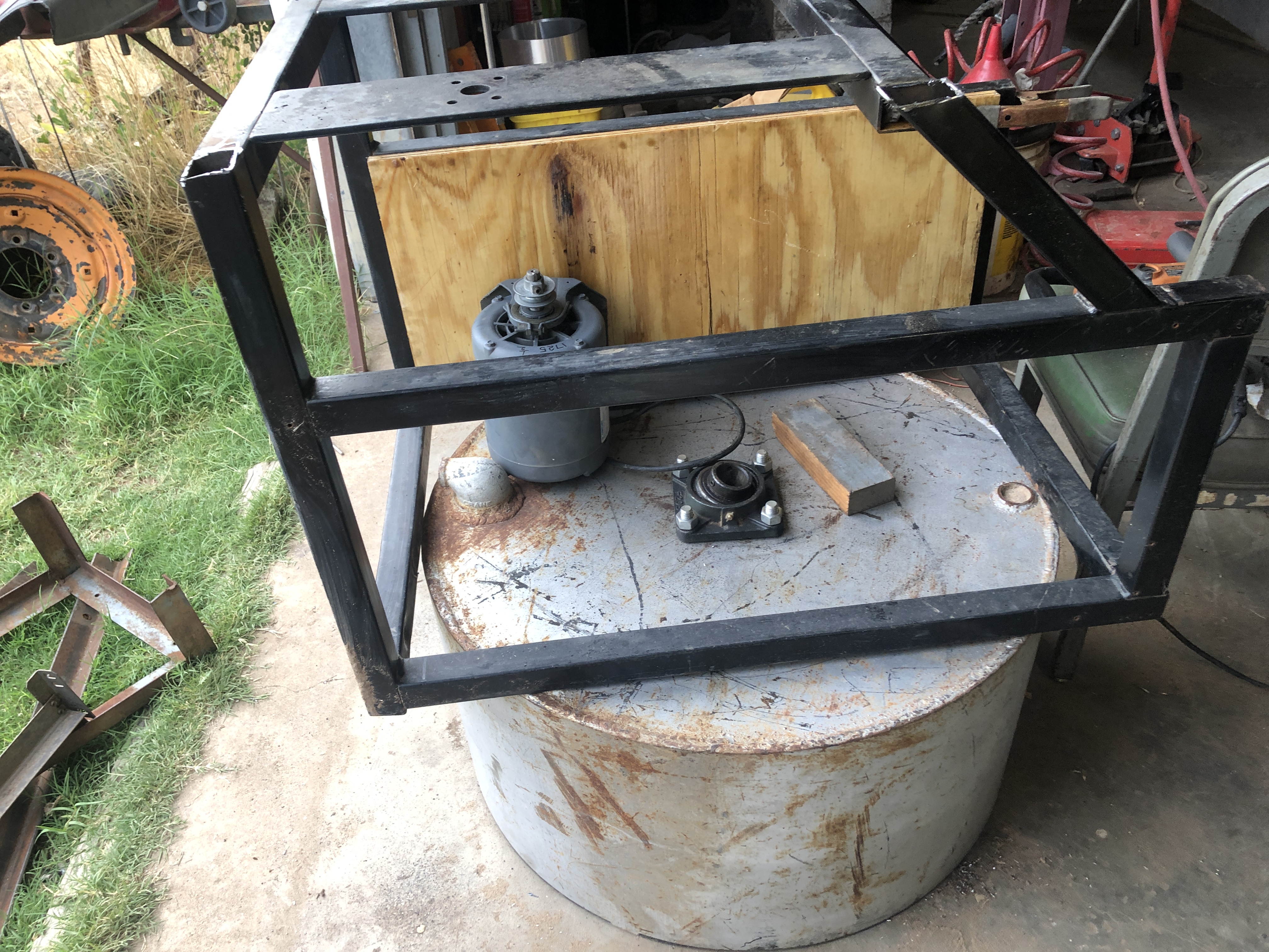
I cut the frame down a bit to make it shorter.   It will attach as shown but yeah its upside down.  The board in the back will hold the pulleys.

  
The frame with the bit I cut off resting on it.With the bit removed


Friday 11:30 AM 

Got my but out to the shop before 7AM.   Yesterday I realized the existing shafts are 7/8" which should be good enough for the 1.5HP setup.  Not too sure on the cushioned bearings but will go with them and see if I need to swap them out.

The blank for the 1st shaft small pulley was already in the Atlas.  Bored and reamed the hole to 5/8".  Yeah found a drill just smaller and the right sized reamer.  Go TEAM!

There is not enough stock to easily finish the pulley in a chuck.  So I set out to make a tapered arbor and turn it between centers.  Found a 3/4" bit of shaft.  About then I got fed up with the lantern tool post never being on center.  Looked just over the other side of the lathe and seen a 3 or 4" long chunk of round steel the same diameter as the big washer on the tool post.   


So I push the arbor onto the stack and start on the tool post spacers that will eliminate the rocker.  Started out intending to make just one size a little over 1/2" tall.  Then I realized I should make a small number to match the various tool holders.  So after drilling about 3/4" in I started over drilling all the way through.
First one parted off.
 

Next I need to part them off.  But I need to turn the jaws around, bump the lump around a bit and face it off again because we want the washers to have an even thickness.  Thinking I may need make up matching shim washers for more exact adjustment.   But maybe not as most of the tools are held at an angle in the tool holder and get taller as they are extended.  The only exception is the boring tool holders.  Once I have this I can setup an off lathe jig that I can use to set the correct height this way when inserting a tool into the holder.  

The tools that come to mind are the left/right/center tool holders.  With luck these are the same.  Parting tool holder.  And the boring bar holder.

So after lunch if its not too hot. First flip the jaws.   Center and face the stock.  Find maybe sharpen the parting tool.   Then part off spacers.   I see the tool post playing musical chairs.  And remember that I can turn a spacer down but can't stretch it!  Maybe write this up a bit in the Lathe Maintenance post.

Did I mention the rocker half moon is currently hiding.  Happened just after I finished boring this morning.  Maybe it will get bored and show itself this afternoon.

Assuming that I have a working tool post.  Get back to making the arbor.  Will do a light pass on the bar to see if the tail stock is centered.  It will give me a starting point in any case.   Then adjust the tail stock to get the needed taper +2 thou on the big end and -2 on the small.    With luck I will get this dialed in prior to hitting the finial size.  

Have the live and dead center, drive plate but no lathe dog.  Actually have one but its way too small.  So I need to make one.  Plan to bolt to square bars together and drill a hole centered at the join to fit the arbor.  Maybe need a small spacer between the stock when its drilled to get compression on the arbor.
I was originally thinking of making this out of aluminum.   Have to see what I have on hand.


template


Monday  July 20

Back to making pulleys.   Have made a mandrel so I don't need to chuck them.  Sharpened a  round nose lathe tool on the Sharp All.  

So now back to making pulleys.  Going to use a 2.5 on both the motor and first shaft.  Motor is a 7/8" ID.

Tuesday July 21


Calculating shaft sizes

Calculating shaft sizes


I think the upper right formula for a shaft with key way applies.

Lets work out what the motor shaft needs to be.
cube root ((40x1.5HP) /1725) = 0.33 in

So now how do I work out the size for the next shaft and the one after that.
HP = torque x RPM so that does not change,  

From a previous post with the addition of RPM for each shaft.

belt  motor 1st shaft 2nd shaft spindle ratio
1: V  2" 10" 5:1
2: V 2.6" 9.75"* 3.75:1
4: flat tooth 2" 8.5" 4:1
RPM172534592 23 75:1


again for the 1.5HP motor
cube root ((40x1.5HP) /1725) = 0.33 in
1st shaft
cube root ((40x1.5HP) /345 = 0.56 in
2nd shaft
cube root ((40x1.5HP) /92 = 0.87 in   (7/8")
spindle
cube root ((40x1.5HP) /23 = 1.38 in

So clearly I will have to up size the 2nd shaft and bearings to use the 1.5 HP

What about the 1/2 HP motor
cube root ((40x0.5HP) /1725) = 0.23 in
1st shaft
cube root ((40x0.5HP) /345 = 0.39 in
2nd shaft
cube root ((40x0.5HP) /92 = 0.60 in
spindle
cube root ((40x0.5HP) /23 = 0.95 in

On this one the 2nd is also weak but maybe close enough to work.  Do what I can to use a shaft without a key way between the pulleys.  Maybe that will belp.

Conclusion

The unit can be built with the existing drive stuff and the 1/2 HP motor.

To upgrade to the 1.5 HP I will need a 1" 2nd shaft and bearings.  Will also need to cast or find a beefier large pulley for the 2nd shaft.  The hub on the existing one can not be bored to an inch.

Hope is that belt 2 will be ok.  Maybe need to double it or go to a poly V. Need to figure out how to calculate that.

Tuesday, July 14, 2020

New way to upload iphone photos into blog


This is a little crazy but it works.

1. Transfer photo from iphone to ipad using airdrop. 

2. From browser open existing blogger entry and insert the photo.

3. Open same entry on PC/linux and do the required edition.


A person with better vision might do this all from the iphone or ipad.  I find it a lot easier to edit on the Ubuntu based PC.

For some reason tables have disappeared from the editor menu.  Copied an existing one and will just replicate it as needed.  Two pictures with captions in the row below.


Monday, July 13, 2020

Muller Build July 13-15


A few days a go I cut the washer come arbor off the 1.5" shaft.   I turned it down.  Had I to do it over I would have cut most of it off first with a angle grinder cut off wheel.   It was my first time using the steady rest other than for coiling wire.

  
 On the left an image of the shaft inserted into the toothed wheel hub.   After the washer was removed and the hub bored.

Shop is starting to look a bit more organized!


Today I cut the V belt groove in the 9 3/4" in pulley.   Bolted it to the 14" face plate.  Everything about this was pushing the limits.   If the cross slide traveled another few inches to the front of the lathe it would have been easy.  Would have been easier if the face plate was not larger than the pulley.

  
 Before  After

That should complete all the drive parts but for mounting.   


This is the bushing I used to align the
bottom bearing so I could drill its
mounting holes.  The small diameter has
been turned down.
It is a slip fit to this thin wall tube from a
chain link fence  The bushing will bolt to
the bottom of the drum and the pipe will
keep sand out of the bearing.

Four holes will be drilled on the flange.  The bush will be slipped over the 1.5" main shaft and the holes marked on the drum with transfer punches.  Then the bush will be removed and the center bored to allow more clearance for the shaft.

During final assembly some sort of sealant will be used between the pipe and bush.   Also need to figure out a top bush that will let the shaft rotate inside the pipe while maintaining spacing should the pipe get bumped.  Maybe HDPE plastic.  Then a cap attached to the shaft that covers the pipe.


Drilling the holes in the flange.Enlarged them to 1/4"


Drilled one hole then with it in place 
marked the other three.
The bolt holes for the flange came out 
very close to the center hole.   One broke 
through and I turned it into a slot.

Obviously this was not as well tough out as it could have been.  But it worked out just right.   The choice of 1/4 hardware here turned out to be a good choice as it was small enough to not get in way of the bearing.  Had I drilled the holes further out on the flange the bolt heads would not have fit inside the bearing holder.  

  
The bolts fit the flange and it seems 
centered.  I plan on enlarging the center 
hole anyway.
A longer section of this pipe will keep sand 
away from the rotating shaft and out of 
the lower bearing.

The pipe needs to be decently centered over the drive shaft.  The shaft is supported on top by a 2nd bearing but the pipe is not.   So thinking of making a HDPE plastic bushing for between the shaft the pipe on the top end of the pipe.  Then a hat over that to keep sand from falling in.
 
Thinking of making a rubber gasket for between the flange and the drum to better keep water and sand out.  Maybe just some RTV.

So what have I accomplished the past few days.

Cut the center hole in the drum
Mounted the lower bearing in the drum.
Removed the arbor/washer from the shaft.
Bored out the big toothed pulley hub to fit the shaft.
Located pulleys. bearings and jack shafts for the drive.
Cut the V groove in the 9 3/4" pulley.


template

Sunday, July 12, 2020

Lathe Maintance

Disassembled and cleaned the Sidney's compound.   Also cleaned and oil the cross slide but did not take it apart.   Too many chips.


The compound on the Atlas only had one pin holding the compound down.  Found a pin and ground it to a similar angle.  Both the new and the old pin are hard.  I don't think this is right.   Also the hole with the empty pin on the atlas has been drilled and tapped to the next size up.  Thinking of bushing this back down to the right size.  Less chance of over tightening.

Have obtained vectra 2 way oil and 2 gallons of 20W non detergent this month.


Thursday, July 9, 2020

Foundry Fluxes


http://prometheus-foundry.com/tutorial.html

Muller Build July 8-11 2020

Trip to Amarillo postponed.

Finished boring the hub to take the 1.5" shaft.  Hub is cast iron.  First time turning with cast iron.  Need to re cut the hub's internal 1/4" keyway.  Should also cut a new keyway in the shaft so as to not use the one cut with an angle grinder.    Need to finish up the power supply for the master mi cut these.  Should have the material to make the bush for the internal broach.

Used a file to enlarge the keyway in my 9 3/4" pulley to fit the keyway on the shaft with the small toothed pulley. 

Found a 1/2 HP 1725 RPM motor to use.  Quite possible its too small but I don't want to fight with a 1.5HP during construction.  Maybe make sure I have holes to mount both.

belt  motor 1st shaft 2nd shaft spindle ratio
 2" 10" 5:1
V 2.6" 9.75"* 3.75:1
flat tooth 2" 8.5" 4:1
 overall 75:1

Should have shafts and bearings from the fitness tables.    If I replace the 2.6" pulley with a 2.5 the RPM will not change much. 22 instead of 23.  Will look for a 2.5.

* If I replace the 9.75" with a 6" the overall ratio becomes  46:1.  1725/46 is 37.5 RPM.   This is starting to seem more reasonable.   But may take the 1.5 HP motor to run it so I will try starting with the 9.75".  EDIT: Or maybe replace the 2.6 with a larger one because I found the 2.5" I have will not fit the shaft.  a 3" results in 3.25:1 or 65:1 overall for 26.5 RPM.

Later EDIT: if the small pulleys on the motor and shaft 1 are replaced with 2.5" pulleys we
get a reduction of 4 x 3.9 x  4 =  62.5.  The 1.5 HP motor is listed as 1740 RPM so 1740/62.4 = ~ 28 RPM.   I am thinking there is too much torque to us a 2 in pulleys.   

Its 100F.   So thinking is better than working. :)

July 9

The heat seems to have gotten to me.   Or maybe just too many hours.  So I am inside in the cool for a while.  Last night I played with the pulleys inside the base.   Was thinking about the support structure for the jack shafts.     The idea of making slots for adjustment without a milling machine is putting me off. 

I have a sheet of decent 1/2" plywood.  I think I will double that up and mount the two jack shafts to it.  Will be a lot easier to make adjustment slots even if I have to make a slot to run the center belt.  Still need to think on this but the tables I am getting most of the pulleys from used plywood for motor mounts.  May work here too especially if it laminate 2 sheets.  Hopefully it will be good enough to keep.  If not it will serve as a prototype.

The wood shop aka garage is cooler than the metal shop so maybe I can work on this in there this afternoon.

Based on the above table

Top will have slots to support the 2nd shaft top bearing and a cutout for the 2" tooth pulley.   
In the middle will be slots for the bottom bearing of the 2nd shaft and top bearing of the 1st shaft and a cutout for the center belt.
The bottom will have slots for the 1st shaft bottom bearing and a cutout for the 2" pulley.

  
To tighten the belts.

Adjust 2nd shaft to tighten top belt.
Adjust 1st shaft to tighten middle belt.
Adjust motor to tighten bottom belt.


Not 100% sure about the location of the pulley on the bottom of the drum.   So maybe leave an extra inch of plywood on top.   

July 10

Its too humid for life as we know it.  Humidity actually.   Installed the window AC unit into the bedroom and closed the door.  Swamp cooler was not cutting it.

Found a scrap of plywood that should work.  5/8 or 3/4".     

Yaking with Chripy on discord today I realized I could replace they keyway on the hub and main shaft with a shear pin.  Thinking I may put copper slugs under the existing set screws to help keep the hub aligned even with the shear pin.

I have also been toying with monitoring the current used by the motor and use a uC to compare that with what I set.  Have it trip on over current.   That would beat any shear pin because there is nothing mechanical to replace. 

Thinking about his the jack shafts are only 1/2"   So more suitable for the 3/4 HP motor.   These can always be upgraded.  Would need to get 4 larger pillow block bearings.   Of buy the bearings and cast the blocks.

July 11

Still thinking about the belts setup but there is something I know I need to do  Machine a V groove the cast aluminum pulley.   It might have been easy if I had machined a register on the inside of the rim.  Maybe a rookie mistake or maybe it would not have been wide enough to serve.   Anyway the only way I can see to machine the groove is to mount the pulley to the 14" face plate on the Sidney lathe.   The grooves in the plate are 1/2" wide.   Rather then use 1/2" bolts I am machining stepped bushings that I will use like T nuts.  Turn on the Atlas then file 2 flat spots to fit the face plate slot.   This is a stouter way then turning the small end to 1/2".    Bolts will go through the bushing/nuts and through plates on face of the pulley.   4 of these should be enough to keep the pulley in place.

Hmm well with the pulley centered only two slots line up.   Either have to drill holes or make do.  I have fairly heavy plates on the pulley side so maybe it will be good enough.

Playing tinker toys with the pulleys axles and bearings to find a solution I like.


Saturday, July 4, 2020

Muller Build July 4 - 7 2020


Cut pipe and plate for a larger crucible.  4 in ID and 9.5 tall.  Works out to 106 ci if filled to one inch from the top.  About 10 lbs of aluminum.  My large cruciable for the Kerr 666 held about 125 ci so I am a bit disappointing but it is what it is. 


Of course this set me thinking about the muller.    Fairly recently I had been thinking of using the old monarch concrete mixer but its really noisy.   So much so I don't want it inside.  So maybe the original plan to use the Twin Cities Hub gearbox is a better choice.  But then I have a better use for that 150:1 double worm drive.  So I think it may come down to belts and pulleys.  Maybe.   But there is plenty else to build in the mean time.

July 5


The first image is the 1.5"  main shaft, bearings and pulley.  These were part of a scary DIY buzz saw setup a fellow made to cut fire wood.   Also shown is some of the engineering that went into it.   I can make use of the keyway and top thread but the washer has to go.  Need a sturdier disk down a few inches from there maybe even a bar with mounting holes.

I can't complain.  Its the bits I need.  The frame this saw was mounted on is now my molding bench. :)


The tub is an old thick wall tank I cut down.  About 30" diameter and 15" tall.  In the first image I was finding the center.  The tank has one flat spot along the wall but its minor.

The tub will stand still with the wheels and paddles rotating.   So I cut a 3" hole in the center to take the 1.5" main shaft.  A smaller hole would have worked but it would have required buying another saw.  The bearings are large enough that the somewhat larger hole will not be a problem.

Need to center the shaft to fit the bearings.   Yeah I could have laid this out prior to cutting the hole but I did not.   So I grabbed an extra cast pulley blank and turned a bushing to center the shaft in the hole.   Turned the outside then drilled a 1" hole in one go and enlarged it with a boring bar. Nice slip fit.  So now I can drop the bearing over the centered shaft and drill the bearing mounting holes.  This bushing may be used on the inside of the tub to help cover the hole and keep sand out of the bearing.  Still thinking about that.

I have to say I am enjoying the six jaw chuck.  Thanks Deb.

I have not selected a motor.   A 1725 rpm moor requires a 75 to 1 reduction to get 23 rpm.  Square root of 75 is 8.7.  Hmm looks like I will need 3 belts.   Cube root of 75 is 4.217.   I am still thinking of.a variable speed from a lawn tractor for one section.  ....nope looked at the only one I have and it is missing parts.  I think.

July 6

Drilled 4 holes to mount the bottom bearing.   These are the self aligning type.  They were reluctant to move so I hit them with carb cleaner then non detergent oil.   Used a transfer punch to mark the first hole then bolted the bearing in place and used the full sized drill to mark the other 3.  So far I have only found one bolt, 0.62" so 5/8" inch.  I may have the ones that came off the saw.

The SO picked up 8 5/8" x 2" bolts with nut washer and lock washer.  Something like 25 or 30 dollars.  Sounds nuts to me. LOL

Turned down the washer that was welded to the shaft.  Took way longer than I expected.  Started setting it up on the atlas and realized maybe the heavier  The 1.5" shaft was too large for the spindle so I had to set up the steady rest.  Had a heck of a time getting it running true.  Switched through 3 different cutting tools and sharpen em a few times.

Cleaned up one of the bearings and figured how to take them apart.  Looks like they are sealed bearing and the grease nipple only greases the self alignment feature.  Should remove the one I just installed in the bottom of the drum and clean it up too.  Don't know why I did not do that first.  Maybe because I morphed from design to building while I was not looking. 

Tomorrow I need to measure and figure a few things out so we can go shopping in Amarillo the next day.  When we get back my little vacation is over and I need to finish the garage.  So won't have much time to spend here.  Sigh.  

Now to transfer some images.


July 7

Time to get back to thinking, scrounging and prototyping.  Need a drive section.  I plan to ignore the wheels and scrapers until after I have a shaft rotating in the drum at a correct RPM.  23 maybe.

  
A small pulley on the motor will drive
this 10".
A small pulley on the previous
shaft drives this 9 3/4". Needs groove.
  
This 2 or 2.5" toothed pulley shares the
previous shaft.
This 8.5" toothed pulley will go on the 
1.5" main shaft.  Need to either bore 
out the hub or cast a new one.


I will be casting and machining a couple of small pulleys to get the ratio right.

Obviously the toothed pulley will not slip so have to reduce tension one or both of the other belts to do so.

Used the press on the side of the hydraulic press brake to push the hub out of the large tooth pulley.  It did not slide out it exploded out.  No damage.  Need to learn to put a blanket under what I am pressing.  With the hub out of the pulley the shaft nearly dropped out of the hub.  So when putting it back together reverse that.   1.5" shaft to hub then put the pulley over the hub.   Might have to press it in so best to put the male end of the hub up so it fits in the press.  Maybe I can tap it on.

Fussed a while about boring out this hub.  There will only be .3 inches of wall left.  But its just a spacer so there should be no problem.  Stuck it in the six jaw.  With the large flange tight against the chuck there is 3 thou runout on the face and about 10 on the outside.  But this thing turns once every 2 seconds it should not matter.  Sigh  Not looking forward to cutting the key way.

Managed to get back into the shop one more time.  Started enlarging the hole in the cast hub for the toothed pulley.  Drilled it out in 1" in several steps   Bored it to about 1.3".   Going to move it over to the Sidney and center it on the 4 jaw to finish it.

This is getting long time to start a new entry.   Tomorrow is shopping in Amarillo and if all goes well I should end up with 500 to 1000 lbs of masonry sand which is supposed to be fine.


Thursday, July 2, 2020

The Craftsman 17" Drill Press

A few days ago Lord of Lava Island on discord asked about our drill presses.  I reported my Craftsman 17 inch has a lot of runout.   I was living with the runout but once I told the world about it things chanced in my mind.   

So I took a DTI to it.  One inch from the chuck I was measuring 5 thou runout.   I swaped in the 1/2" Nova chuck I use on the wood working and Atlas lathes.  Same bar same location showed less then 1 thou run out.

Tried to unscrew the MT2 from the drill presses 5/8" chuck.  Failed.  But now realize that it could well be a  JT33 taper and I can possibly drive it out with a punch between the jaws.  A new MT2-JT33 taper is only $14 while a new chuck of decent quality is more like $50 and up.

The atlas came with a MT2 1/2" chuck    I should check it while I am at it.  

TO BE CONTINUED