
Tried gluing the paper pattern to the plans but it was miserable. Switched to layout fluid and scratching with the digital caliper and scribe. I was able to find the intersection of lines with the tip of the automatic center punch, thanks Chirpy.
 As it currently existed the DIY fence on the 4' hydraulic finger brake (discussed elsewhere in this blog) did not come close enough to the die. But its just a chunk of angle iron bolted to a butchered 4x4 so some quality time with a forstner bit allowed it to accommodate the offending bolts.
 The angle parts were cut from a lawn tractor frame. Its 1/8" just a bit over the 3 mm called for in the plans.

Filing buttons were used to shape the curves. The paper covered part to the right is a failed attempted at using paper templates glued to the steel. I guess that's just for wood.
The slot in the links were chain drilled then an 1/8" end mill was used in the drill press to clean it up to where I could use a full sized file.
 The friction disks that hold the unit in position were cut from 3/16" hot rolled steel using a hole saw.
1/4" bolts were used a mandrels. A nylock nut captured the disk on the bolt which was inserted in the collet to turn the OD and bevel one side.
Here I drilled a center in the bolt but did not use is. Similar but longer mandrel/bolts were used to turn the OD of the aluminum spreaders and the tailstock was used to support them.

The friction disks after turning. At this point I still have to cut the groove on the other side for the o-ring.
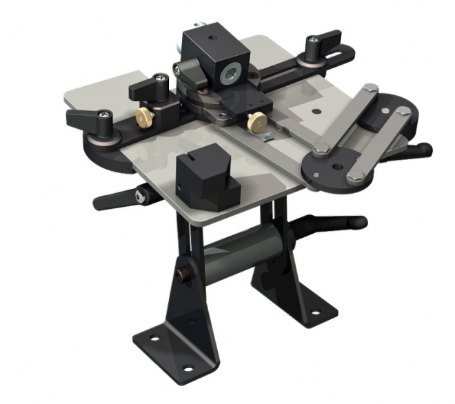
And at this point I have what is show in the first photo.The following image from Ecentric Engineering's site shows it loaded with accessories. My initial intent is to sharpen lathe tools so I will not be building the fence and other stuff I don't need.
I may try 3D printing some of the parts. Yeah grinding and plastic are not a good match but let's see how it goes.
------------------------------------------------------------------------
Busted the tip off the grooving tool as I was finishing the first friction disk o-ring groove. Used the table with a filing button standing in for the unfinished friction disk. I have the table bolted to a board that is clamped to the board holding the grinder. I became obvious that I needed to grind on both left and right side of the cup wheel. OR IS IT??? The table was designed for a standard grinding wheel so it is to short. I was able to reposition the table using the clamps but it is far from idea. Thinking about making a much wider version. Really just a wider table and wider spacers. Might require modifications to the bits on top the table.
Have the grinder clamped to the roll around table (bit of scaffolding). So I ran it outside to true up the lip of the cup wheel. My diamond wheel dresser is in hiding so I used a stack of lock washers on a 1/4" bolt. After that I adjusted the table and set to regrinding the broken bit.
Having said that it worked wonderfully. Not sure if the shape is correct but the grinding was easy even fun. The wonder of using a balanced wheel or maybe the cup wheel contributed. All good.
When mounting getting the table true to the wheel is a bit daunting. Maybe replace the two lower brackets with a single U shaped part with a central single mounting hole. That would allow the table to rotate to align with the wheel. Just need to work out how to keep it from moving. Should not be a big deal maybe just torquing it down will be enough. Making the bends will be interesting.
Need to workout a wheel guard. There is not much room between the back of the wheel stack and the motor. So maybe a plate similar in thickness to the original guards with a cast aluminum tube that bolts to it. If there is any dishing to the original plate that bolts to the motor I may have to cut the backing plate from it. Would rather not ruin it. Just in case I want to use this unit with regular wheels some time.
----------------------------------------------------------
I am thinking of making two more units with larger tables more suited to the cup wheels. This will also require new spacers.
Maybe add a second bolt on layer to form a miter slot. It will allow simple jigs to sharpen bits till the rest of the system is finished. Don't need that till I need to sharpen milling cutters.
Maybe add a second bolt on layer to form a miter slot. It will allow simple jigs to sharpen bits till the rest of the system is finished. Don't need that till I need to sharpen milling cutters.
Found an interesting vid on 1 Hour Red Rust Bluing on theCogWheel channel. An hour is a bit painful but there are no chemicals to buy other than common household items.
No comments:
Post a Comment