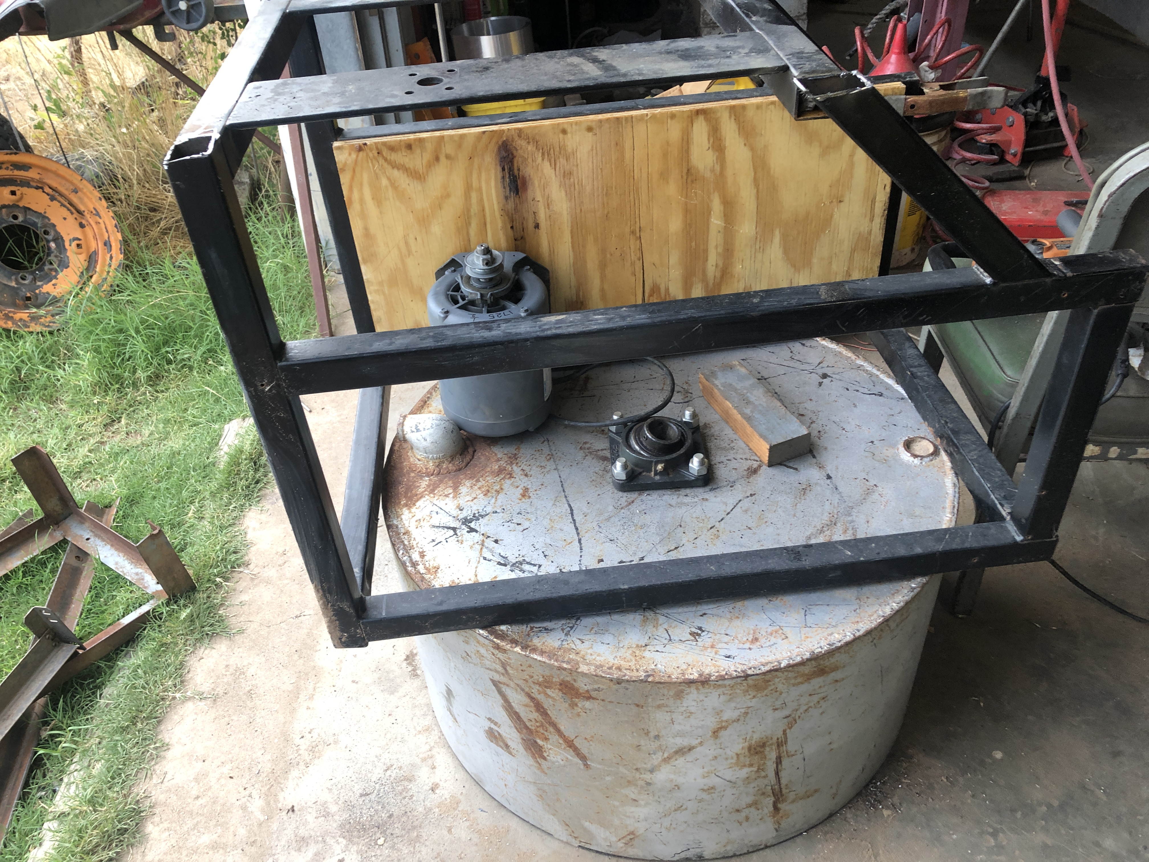
Left to do
Maybe in this order
- Mount the drum to the stand
- Make a mount for the top bearing.
- Cobble together the drive bits.
- Make the arm, plows and roller(s)
- Make the trap door for emptying
- Wheels and maybe a fold up or detachable hitch
Mounting the drum
But the belt setup going to the drum is a fixed length which means the location of the drum and and 2nd spindle are inter dependent. I want the drum centered left to right but can fudge a few inches front to back. Need to mock this up. Again.
I am not crazy about welding mounting brackets to the bottom of the drum. Maybe use long angle iron running front to back and weld on the outside perimeter of the drum where there is already a weld. Perhaps a few tacks along the bottom if needed.
If I don't need to make the drum adjustable for belt tension, and I don't think I will. It can be attached to these angles with pins instead of bolts. The idea is that if for some reason I need to break it down it would be a lot faster if it did not require wrenches.
The drum can be mounted with just 2 angle irons which run along the outside of the frame. I can add these mounts and hold off on drilling holes for pins or bolts until I get the drive sorted. There are 2 fair sized runs of angle iron left from the saw. Maybe these can be used, trying not to use bed frame.
11AM
Attempted to accomplish this with no luck. Played with the parts and figured maybe I should cut the stand down. It and my deep drum together are too much. I can take 10 inches off the stand and it will provide a more stable base. Was thinking about mounting the drive on the end but realized the side might be a better deal. Less folding, or changing direction. The small 2.5" pulley I selected for the 1st shaft will not work. Its hole is too small. Found that after pulling it off a motor. Need to take another look around and if I can't find on I will turn one. Leave a stub on it for chucking it in the lathe. The I can make it a bit over size and turn it down to get it right. If I end up sizing this shaft too there will be plenty of meat for the larger shaft. So it looks like I need to turn two pulleys. Luckily I 'THINK" I already have cast blanks that will works. So that will be my afternoon. But first I want to make the missing pin from the Atlas lathe compound. With luck I can find a pin in the assorted unknowns and bevel the end to match instead of turning one down.
This is wrong. The 2" pulley on the second shaft already exists it is the small toothed pulley.
Maybe the top bearing mount should also be a quick release type of thing. Make changing out the stuff inside the drum easier. That way I can do things other than mull sand. No plans but would like the option.
I cut the frame down a bit to make it shorter. It will attach as shown but yeah its upside down. The board in the back will hold the pulleys.
 |  |
| The frame with the bit I cut off resting on it. | With the bit removed |
Friday 11:30 AM
Got my but out to the shop before 7AM. Yesterday I realized the existing shafts are 7/8" which should be good enough for the 1.5HP setup. Not too sure on the cushioned bearings but will go with them and see if I need to swap them out.
The blank for the 1st shaft small pulley was already in the Atlas. Bored and reamed the hole to 5/8". Yeah found a drill just smaller and the right sized reamer. Go TEAM!
There is not enough stock to easily finish the pulley in a chuck. So I set out to make a tapered arbor and turn it between centers. Found a 3/4" bit of shaft. About then I got fed up with the lantern tool post never being on center. Looked just over the other side of the lathe and seen a 3 or 4" long chunk of round steel the same diameter as the big washer on the tool post.
 | So I push the arbor onto the stack and start on the tool post spacers that will eliminate the rocker. Started out intending to make just one size a little over 1/2" tall. Then I realized I should make a small number to match the various tool holders. So after drilling about 3/4" in I started over drilling all the way through. |
| First one parted off. |
|
Next I need to part them off. But I need to turn the jaws around, bump the lump around a bit and face it off again because we want the washers to have an even thickness. Thinking I may need make up matching shim washers for more exact adjustment. But maybe not as most of the tools are held at an angle in the tool holder and get taller as they are extended. The only exception is the boring tool holders. Once I have this I can setup an off lathe jig that I can use to set the correct height this way when inserting a tool into the holder.
The tools that come to mind are the left/right/center tool holders. With luck these are the same. Parting tool holder. And the boring bar holder.
So after lunch if its not too hot. First flip the jaws. Center and face the stock. Find maybe sharpen the parting tool. Then part off spacers. I see the tool post playing musical chairs. And remember that I can turn a spacer down but can't stretch it! Maybe write this up a bit in the Lathe Maintenance post.
Did I mention the rocker half moon is currently hiding. Happened just after I finished boring this morning. Maybe it will get bored and show itself this afternoon.
Assuming that I have a working tool post. Get back to making the arbor. Will do a light pass on the bar to see if the tail stock is centered. It will give me a starting point in any case. Then adjust the tail stock to get the needed taper +2 thou on the big end and -2 on the small. With luck I will get this dialed in prior to hitting the finial size.
Have the live and dead center, drive plate but no lathe dog. Actually have one but its way too small. So I need to make one. Plan to bolt to square bars together and drill a hole centered at the join to fit the arbor. Maybe need a small spacer between the stock when its drilled to get compression on the arbor.
I was originally thinking of making this out of aluminum. Have to see what I have on hand.
Monday July 20
Back to making pulleys. Have made a mandrel so I don't need to chuck them. Sharpened a round nose lathe tool on the Sharp All.
So now back to making pulleys. Going to use a 2.5 on both the motor and first shaft. Motor is a 7/8" ID.
Tuesday July 21